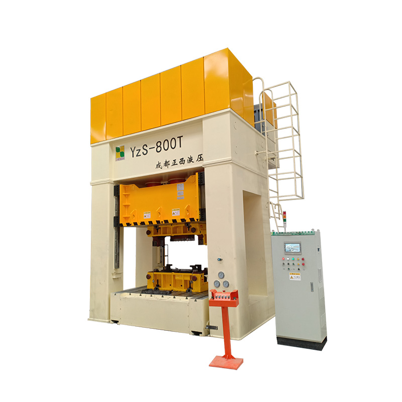
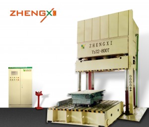
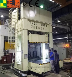
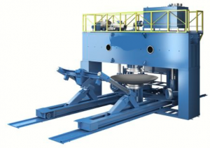
800T H-frame Deep Drawing Press Machine
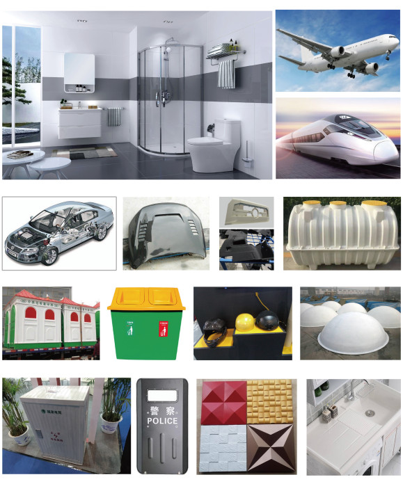
ZHENGXI SMC BMC Hydraulic Press also called hydraulic composites molding press, it is applied in compression moulding of composites material such as SMC,BMC,FRP,GRP and so on. Our SMC Forming presses and press offer the composite industry superiour production capabilities, as well as repair and upgrade options. We are supplying new customs hydraulic molding presses, and ZHENGXI aslo provides a comprehensive list of repair and upgrade options for existing compression molding presses of all makes and models. Our hydraulic molding presses are used to produce an extensive variety of innovative automotive, aerospace, industrial etc. Whatsapp: +86 176 0282 8986
Machine Features
It is mainly used for the integral forming of thermosetting (FRP) plastics and thermoplastic products. Suitable for the forming of SMC, BMC, DMC, GMT and other bulks and sheets.
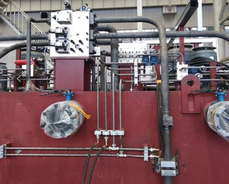
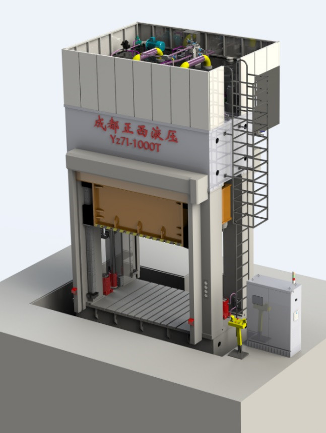
Hydraulic system is installed on the top with maintenance platform, environmentally friendly, low noise and easy maintenance.
Multiple-stage slow speed pressure forming, reasonable reserved exhaust time.
With the function of high pressure slow opening mold, suitable for high products.
Quick response of system, numerical control system.
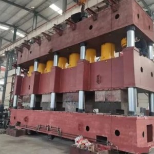
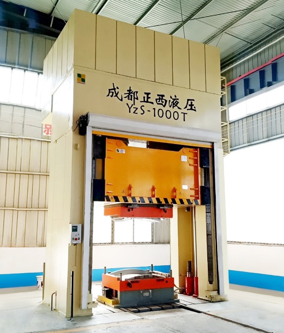
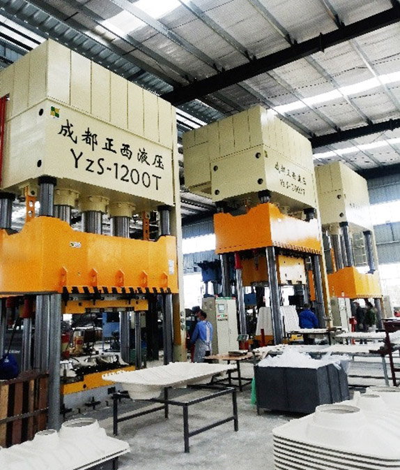
On Site Picture
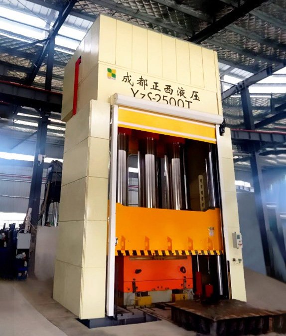
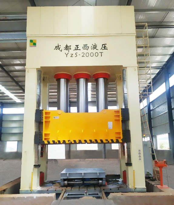
Applications
This machine is mainly suitable for composite material molding; the equipment has good system rigidity and high precision, high life and high reliability. The process for hot press forming meets 3 shifts/day production.

Manufacturing Standards
| JB/T3818-99 《Technical conditions of hydraulic press》 |
| GB/T 3766-2001 《General technical requirements for hydraulic systems》 |
| GB5226.1-2002 《Safety of machinery-Mechanical and electrical equipment-Part 1: General technical requirements》 |
| GB17120-97 《Press machinery safety technical requirements》 |
| JB9967-99 《Hydraulic machine noise limit》 |
| JB/T8609-97 《Press machinery welding technical conditions》 |
3D Drawing
H frame type
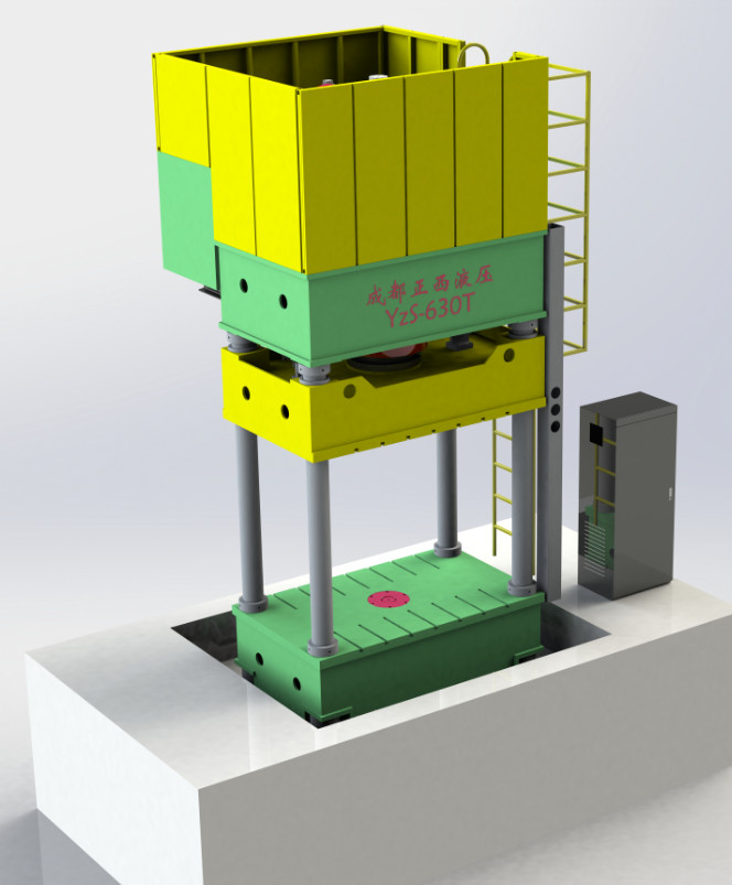
4 column type
Machine Parameters
| Item | Unit | YZ71-4000T | YZ71-3000T | YZ71-2500T | YZ71-2000T | YZ71-1500T | YZ71-1000T |
| Pressure | kN | 40000 | 30000 | 25000 | 20000 | 15000 | 10000 |
| Max. liquid pressure | Mpa | 25 | 25 | 25 | 25 | 25 | 25 |
| Daylight | Mm | 3500 | 3200 | 3000 | 2800 | 2800 | 2600 |
| Stroke | Mm | 3000 | 2600 | 2400 | 2200 | 2200 | 2000 |
| Working table size | Mm | 4000×3000 | 3500×2800 | 3400*2800 | 3400*2600 | 3400*2600 | 3400*2600 |
| Height above the ground | Mm | 12500 | 11800 | 11000 | 9000 | 8000 | 7200 |
| Foundation depth | mm | 2200 | 2000 | 1800 | 1600 | 1500 | 1400 |
| Down speed | Mm/s | 300 | 300 | 300 | 300 | 300 | 300 |
| Working speed | Mm/s | 0.5-5 | 0.5-5 | 0.5-5 | 0.5-5 | 0.5-5 | 0.5-5 |
| Return speed | Mm/s | 150 | 150 | 150 | 150 | 150 | 150 |
| Total Power | kW | 175 | 130 | 120 | 100 | 90 | 60 |
Main Body
The design of the whole machine adopts computer optimization design and analyzes with finite element. The strength and rigidity of the equipment are good, and the appearance is good. All welded parts of the machine body are welded by high-quality steel mill Q345B steel plate, which is welded with carbon dioxide to ensure the welding quality.
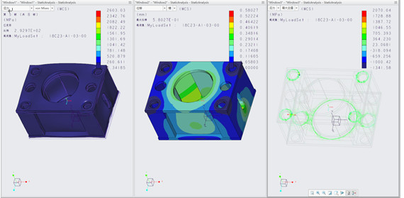
Cylinder
|
Parts |
Feature |
|
Cylinder Barrel |
|
|
Piston Rod |
|
|
Seals |
Adopt Japanese NOK brand quality sealing ring |
|
Piston |
Guided by copper plating, good wear resistance, ensuring long-term operation of the cylinder |
Pillar
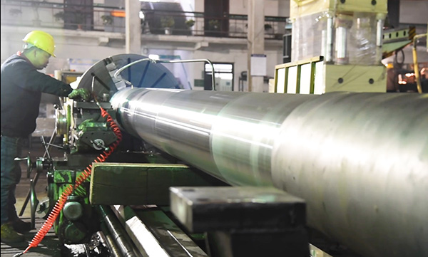
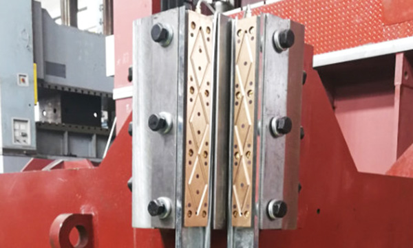
The guide columns (pillars) will be made of C45 hot forging steel and have a hard chrome coating thickness 0.08mm. And do hardening and tempering treatment. The guide sleeve adopts copper guide sleeve, which is more wear-resistant and improves the stability of the machine
Servo System
1.Servo System Composition
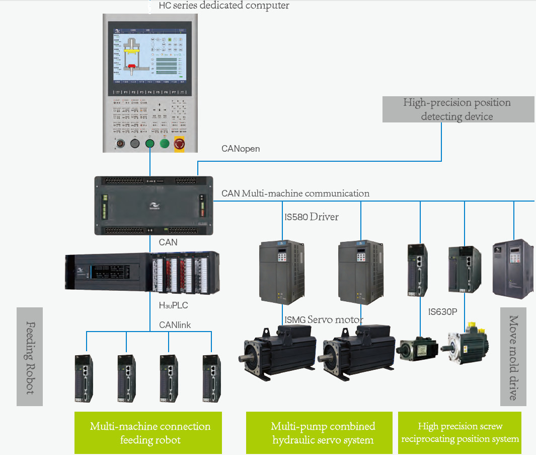
2.Servo System Composition
|
Name |
Model |
Picture |
Advantage |
|
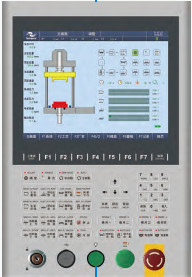
HMI |
Siemens |
|
The life of the button is strictly tested, and it is not damaged by pressing 1 million times.
Screen and machine fault help, describe screen functions, explain machine alarms, and help users quickly master the machine usage
|
|
Name |
Model |
Picture |
Advantage |
|
PLC |
Siemens |
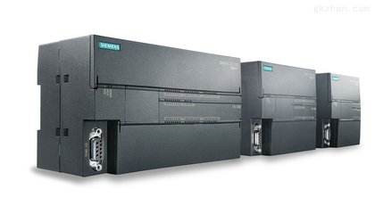
|
Electronic ruler acquisition line is processed independently, with strong anti-interference ability
Digital control of the servo drive and integration with the drive |
|
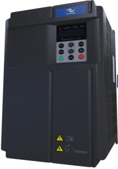
Servo Driver
|
YASKAWA |
|
The overall busbar capacitor is fully upgraded, and the capacitor with wider temperature adaptability and longer service life is used, and the theoretical life is increased by 4 times;
The response at 50Mpa is 50ms, the pressure overshoot is 1.5kgf, the pressure relief time is 60ms, and the pressure fluctuation is 0.5kgf.
|
|
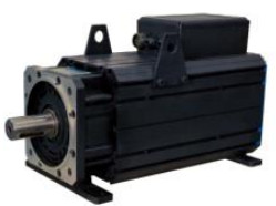
Servo Motor
|
PHASE Series |
|
The simulation design is carried out by Ansoft software, and the electromagnetic performance is superior;Using high-performance NdFeB excitation, the iron loss is small, the efficiency is higher, and the heat is smaller;
|
3.Advantages of Servo System
Energy saving

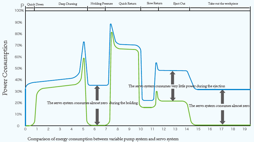
Compared with the traditional variable pump system, the servo oil pump system combines the fast stepless speed regulation characteristics of the servo motor and the self-regulating oil pressure characteristics of the hydraulic oil pump, which brings huge energy saving potential, and the energy saving rate can reach up to 30%-80%.
Efficient
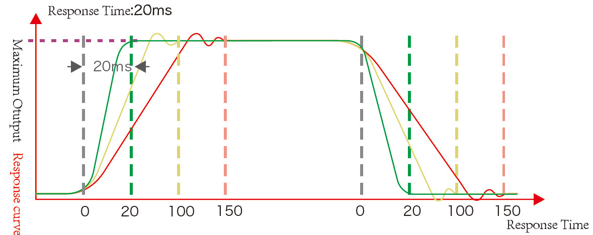
The response speed is fast and the response time is as short as 20ms, which improves the response speed of the hydraulic system.
Precision
The fast response speed guarantees the opening and closing accuracy, the position accuracy can reach 0.1mm, and the special function position positioning accuracy can reach ±0.01mm.
The high-precision, high-response PID algorithm module ensures stable system pressure and pressure fluctuations of less than ±0.5 bar, improving product quality.
Environmental protection
Noise: The average noise of the hydraulic servo system is 15-20 dB lower than that of the original variable pump.
Temperature: After the servo system is used, the hydraulic oil temperature is reduced overall, which enhances the life of the hydraulic seal or reduces the power of the cooler.
Safety Device
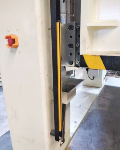
Photo-Electrical Safety Guard Front & Rear
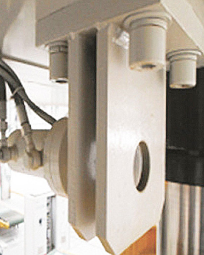
Slide Locking at TDC
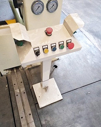
Two Hand Operation Stand
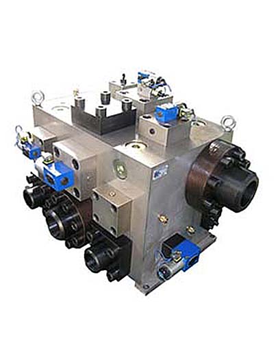
Hydraulic Support Insurance Circuit
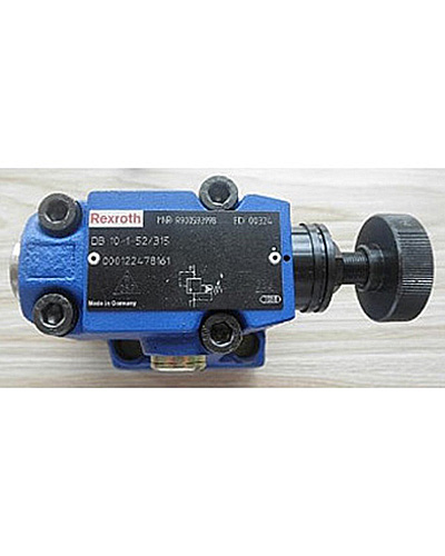
Overload Protection: Safety Valve
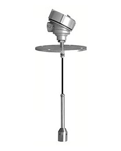
Liquid Level Alarm: Oil level
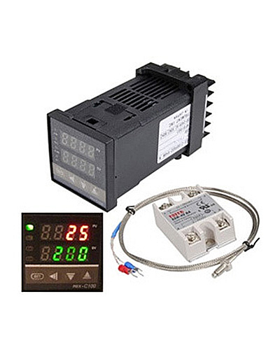
Oil temperature Warning
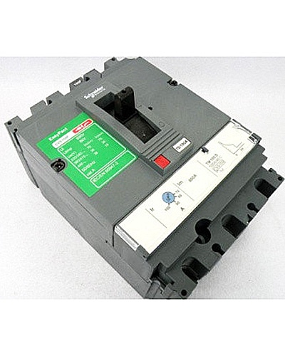
Each electrical part have overload protection
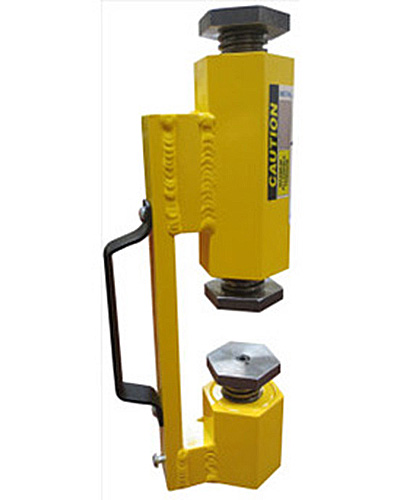
Safety blocks
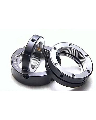
Lock nuts are provided for movable parts
All action of press have safety interlock function, e.g. movable worktable will not work unless cushion return to initial position. Slide can not press when movable worktable is pressing. When conflict operation happen, alarm shows on touch screen and show what's the conflict.
Hydraulic System
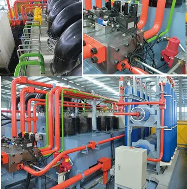
1.Oil tank been set forced cooling filtering system(industrial plate-type water cooling device, cooling by circulating water, oil temperature≤55℃,make sure machine can steadily pressing in 24 hours.)
2.The hydraulic system adopts integrated cartridge valve control system with fast response speed and high transmission efficiency.
3.The oil tank is equipped with an air filter to communicate with the outside to ensure that the hydraulic oil is not polluted.
4.The connection between the filling valve and the fuel tank uses a flexible joint to prevent vibration from being transmitted to the fuel tank and completely solve the problem of oil leakage.
