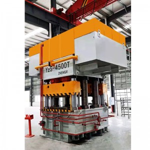
Anti-theft door embossing hydraulic press

Company Case
Application
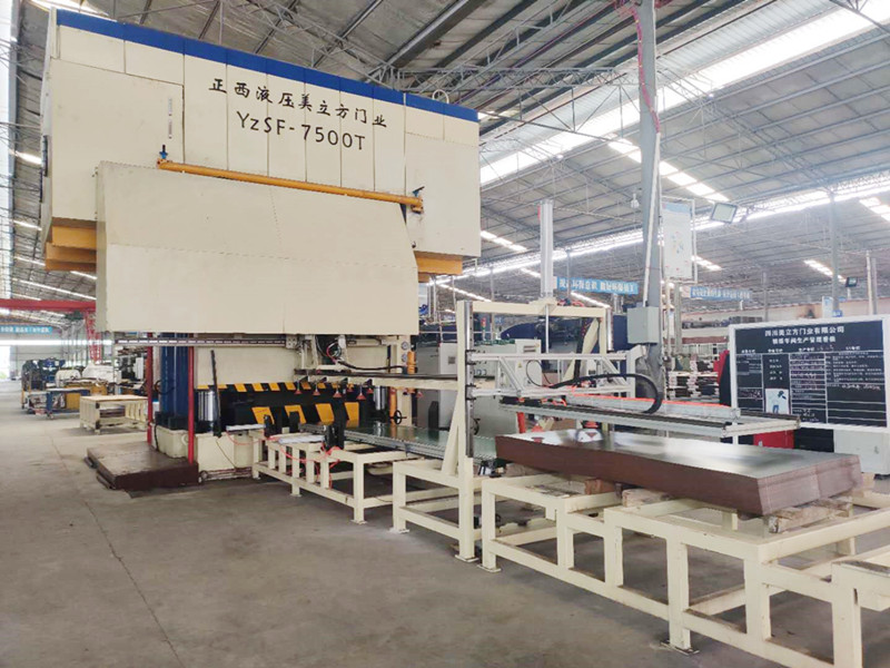
This machine is mainly suitable for metal door embossing. The equipment has good system rigidity and high precision, high life and high reliability. The embossing process for sheet metal parts meets 3 shifts/day production..

Machine Parameters
|
Name |
Unit |
Value |
Value |
Value |
Value |
|
|
Model |
|
Yz91-4000T |
Yz91-3600T |
Yz91-2500T |
Yz91-1500T |
|
|
Main cylinder force |
KN |
40000 |
36000 |
25000 |
15000 |
|
|
Daylight |
mm |
500 |
500 |
500 |
500 |
|
|
Main cylinder Stroke |
mm |
400 |
400 |
400 |
400 |
|
|
Cylinder Qty. |
/ |
6 |
6 |
6 |
6 |
|
|
Table size
|
LR |
mm |
1600 |
1600 |
1400 |
1400 |
|
FB |
mm |
2600 |
2600 |
2400 |
2400 |
|
|
Slider speed |
Down |
mm/s |
80-120 |
80-120 |
80-120 |
80-120 |
|
Return |
mm/s |
100 |
100 |
100 |
100 |
|
|
Working |
mm/s |
10-15 |
10-15 |
10-15 |
10-15 |
|
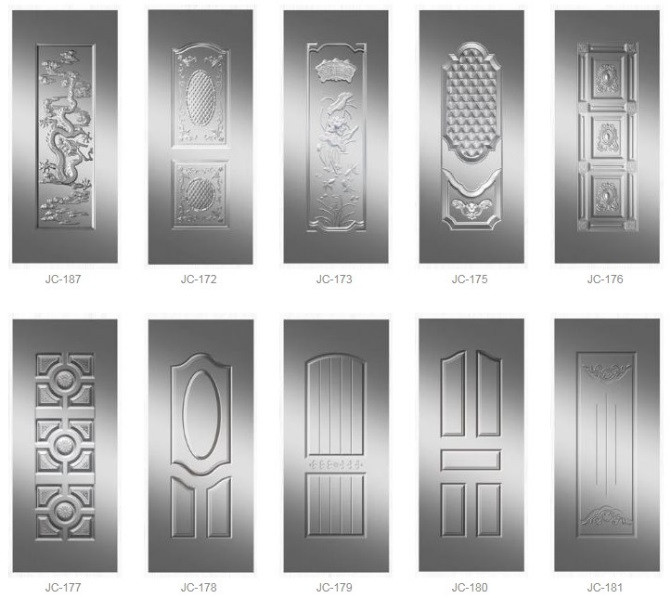
Door Mold and Patterns
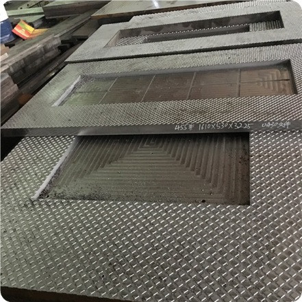
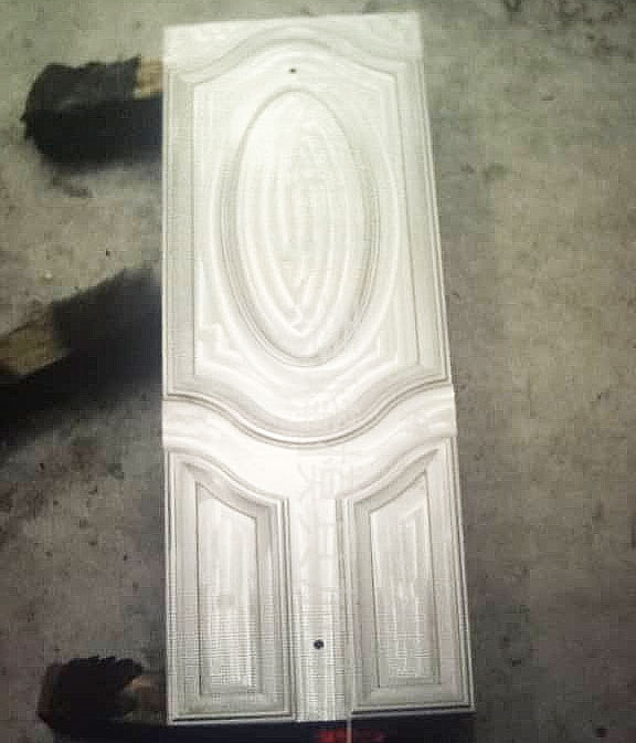
We can provide different patterns for customers to choose, we can provide molds. The mould will be tested in our factory.
The mold contains 1 set of mold frame and multiple sets of mold cores, customer can make different pattern, and only need to buy 1 set of mold frame.
Safety Device
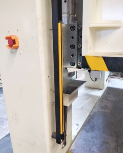
Photo-Electrical Safety Guard Front & Rear
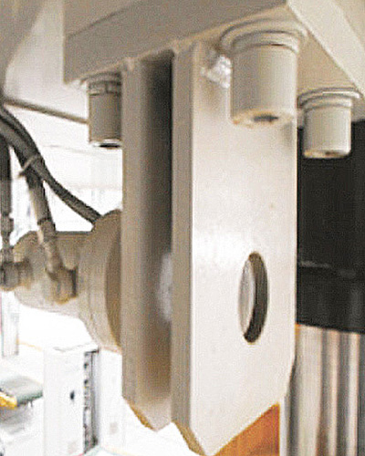
Slide Locking at TDC
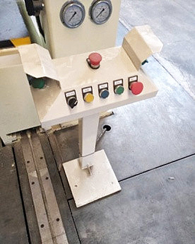
Two Hand Operation Stand
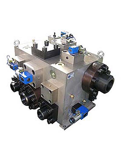
Hydraulic Support Insurance Circuit
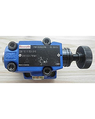
Overload Protection: Safety Valve
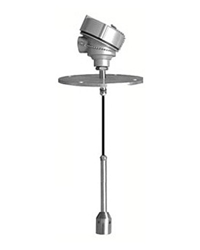
Liquid Level Alarm: Oil level
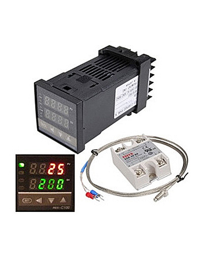
Oil temperature Warning
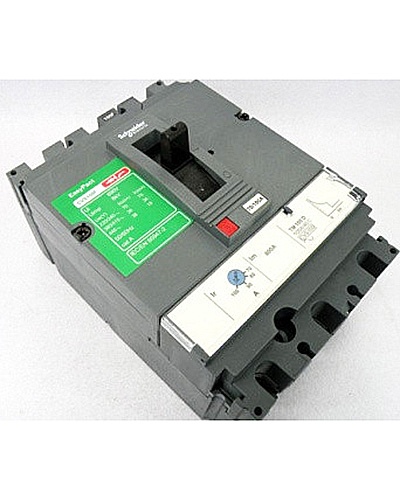
Each electrical part have overload protection
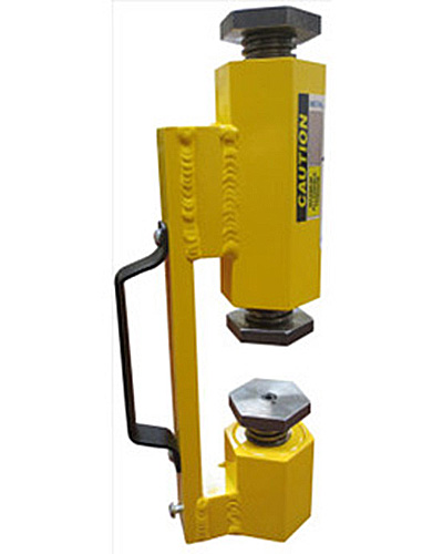
Safety blocks
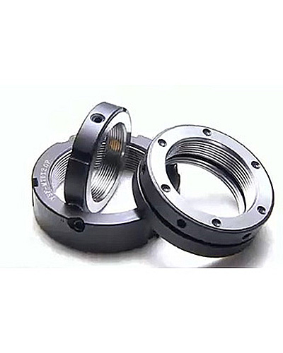
Lock nuts are provided for movable parts
All action of press have safety interlock function, e.g. movable worktable will not work unless cushion return to initial position. Slide can not press when movable worktable is pressing. When conflict operation happen, alarm shows on touch screen and show what's the conflict.
Electrical Control System
1. The electrical system consists of power circuit and control circuit. The power circuit is 380V, 50HZ, which is responsible for starting, stopping and protecting the oil pump motor. The control circuit system adopts PLC programmable controller combined with touch screen main control to realize various process action cycles of the machine tool.
2. The main power distribution control components are installed in the main control cabinet, and the main control cabinet is placed on the ground on the right side of the fuselage; the equipment execution components are connected by soft wires, the main cabinet outlets are regular, and the control lines are connected by aviation plug-ins for easy disassembly With overhaul.
3. The core function of the control part is assumed by the "PLC" programmable logic controller. According to the needs of the process, the commands issued by the main control components (selection switches, buttons, etc.), based on the signals measured by the detection elements such as displacement sensors, travel switches, pressure sensors, etc., process the switching and analog values of the machine and drive The hydraulic pilot valve and other devices realize the control of the pressure and displacement of the hydraulic actuator-cylinder, and then complete the production process of the machine.
The stroke of the slider is controlled by an absolute displacement sensor. The displacement sensor is arranged on the upper part of the inside of the column. The stroke and position conversion point can be directly set and displayed on the touch screen. In addition, there are upper and lower limit switches for double protection in unexpected situations.
4. The centralized operation control panel of the equipment is arranged on the main control cabinet, and the touch panel industrial display screen, working status indicator light and necessary operation buttons and selection switches are arranged on the panel.The electrical system consists of power circuit and control circuit. The power circuit is 380V, 50HZ, which is responsible for starting, stopping and protecting the oil pump motor. The control circuit system adopts PLC programmable controller combined with touch screen main control to realize various process action cycles of the machine tool.
The main power distribution control components are installed in the main control cabinet, and the main control cabinet is placed on the ground on the right side of the fuselage; the equipment execution components are connected by soft wires, the main cabinet outlets are regular, and the control lines are connected by aviation plug-ins for easy disassembly With overhaul.
5. The core function of the control part is assumed by the "PLC" programmable logic controller. According to the needs of the process, the commands issued by the main control components (selection switches, buttons, etc.), based on the signals measured by the detection elements such as displacement sensors, travel switches, pressure sensors, etc., process the switching and analog values of the machine and drive The hydraulic pilot valve and other devices realize the control of the pressure and displacement of the hydraulic actuator-cylinder, and then complete the production process of the machine.
The stroke of the slider is controlled by an absolute displacement sensor. The displacement sensor is arranged on the upper part of the inside of the column. The stroke and position conversion point can be directly set and displayed on the touch screen. In addition, there are upper and lower limit switches for double protection in unexpected situations.
6. The centralized operation control panel of the equipment is arranged on the main control cabinet, and the touch panel industrial display screen, working status indicator light and necessary operation buttons and selection switches are arranged on the panel.

Hydraulic System
Feature:
1. Oil tank been set forced cooling filtering system(industrial plate-type water cooling device, cooling by circulating water, oil temperature≤55℃,make sure machine can steadily pressing in 24 hours.
2. The hydraulic system adopts integrated cartridge valve control system with fast response speed and high transmission efficiency.
3. The oil tank is equipped with an air filter to communicate with the outside to ensure that the hydraulic oil is not polluted.
4. The connection between the filling valve and the fuel tank uses a flexible joint to prevent vibration from being transmitted to the fuel tank and completely solve the problem of oil leakage.


Technical Motion
1. The press machine can be operated in 4 modes: adjustment (Inching), manual, semi-automatic and full-automatic, the working mode also can be divided into 2 modes: constant-distance forming and constant-pressure forming
2. Constant-distance mode: When the current positions of slide and cushion reach a preset position, the current work is stopped. The constant-distance value of the slides are within the range of slide full stroke.
3. Constant-pressure mode: When the current pressures of the slide and cushion reach a preset pressure, the current work is stopped.
4. Adjustment(inching): Operate corresponding functional buttons to complete corresponding actions. Pressing a button for one time makes the press machine complete one-time inching. The press machine is stopped when the button is released. This mode is mainly used to adjust the press machine and replace a die.
5. Manual: Push each function button to complete a matching action, each push complete 1 action a time.
6. Semi-automatic: Double-hand push button to complete a single cycle: When a double-hand button is pressed, the press machine completes a set of process actions (Cycle process should be preset )
Welding Specification Of Main Body
|
Style |
T.L.C.H |
K.B |
Demand |
|
|
A-side H=T2/3 B-side H=T1/3 C≥4 L≤3 |
A-side 60° B-side 35° 1/4≤K≤T |
two-sided tack-weld first then back-weld, last cosmetic-weld |
|
Cylinder bottom
|
According to Drawing |
According to Drawing |
two-sided tack-weld first then back-weld, after cosmetic-weld preserve the heat |
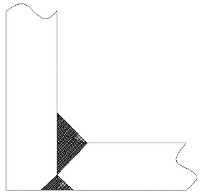 |
A-side H=T/2 B-side H=T/3 C≥4 L≤3 |
A-side 60° B-side 35° 1/4≤K≤10 |
two-sided tack-weld first then back-weld, last cosmetic-weld |
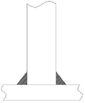 |
V-shape groove H=T/3 C≥4 L≤3 |
40o≤B≤60o 1/4≤K≤8 |
two-sided tack-weld first then back-weld, last cosmetic-weld |
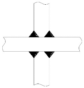 |
Double-V groove H=T/3 C≥4 L≤3 |
40o≤B≤60o 1/4≤K≤8 |
two-sided tack-weld first then back-weld, last cosmetic-weld |
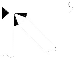 |
V-shape Groove H=T/3 C≥4 L≤3 |
40o≤B≤60o 1/4≤K≤8 |
T-shape processing like above, sloping plate welding after T-shape finished |
|
|
V-shape groove H=T2/3 C≥4 L≤3 |
B≤60o 1/4≤K≤10 |
tack-weld first then back-weld, last cosmetic-weld |
Table Of Tolerance Of Body Structure
|
Structure |
Item |
Tolerance |
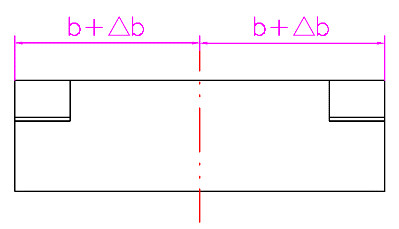 |
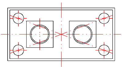
Symmetry of External Elements of Fuselage Structure(Spacing tolerance △ b) |
b≤1000 △b≤1.5 1000<b≤200 △b≤2.0 b>2000 △b≤3.0 |
 |
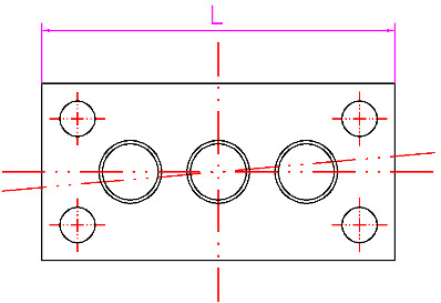
Fuselage structure rectangular(diagonal L tolerance △ L) |
L≤2000 △L≤3.0 2000<L≤4000 △L≤4.0 L>4000 △L≤5.0 |
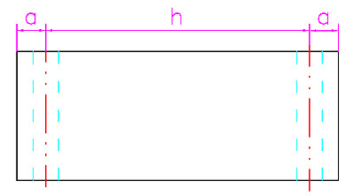 |
Parallelism between Top and Ground of Column Structure t(Inclination Including Upper and Lower Plates) |
h≤4000 t≤2.0 4000<h≤8000 t≤3.0 h>8000 t≤5.0 |
 |
Misalignment of upper and lower boards of fuselage structure |
L≤2000 t≤2.0 L>2000 t≤3.0 |
Tolerance Of Welding Angle
|
Grade |
Short Edge Size mm |
|||
|
≤315 |
>315~1m |
>1~2m |
>2m |
|
|
A |
≤1.5 |
≤2.0 |
≤2.5 |
≤3.0 |
|
B |
≤2.5 |
≤3.0 |
≤3.5 |
≤4.0 |
|
A |
±20′ |
±15′ |
±10′ |
_ |
|
B |
±1° |
±45′ |
±30′ |
_ |
Tolerance Of Welding Shape And Position
|
Grade |
Basic Size mm |
|||||
|
≤315 |
>315~1 |
>1~2m |
>2~4m |
>4~8m |
>8m |
|
|
A |
1.0 |
1.5 |
2.0 |
3.0 |
4.0 |
5.0 |
|
B |
2.0 |
3.0 |
4.0 |
6.0 |
8.0 |
10.0 |
|
C |
3.0 |
5.0 |
9.0 |
11.0 |
16.0 |
20.0 |




 butt joint
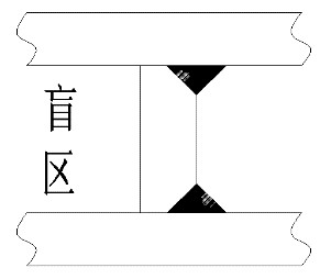 BlindZone